Tagged: trace, trial cell
- This topic has 2 replies, 2 voices, and was last updated 5 years, 1 month ago by
RuslanY.
-
AuthorPosts
-
14 May 2021 at 08:34 #6493
RuslanY
ParticipantHello Nazca-design Team!
Thanks for the extremely handy design tool. I am a beginner nazca user and want to understand this better for experimentation in our university laboratory. I have several questions about creating simple optical elements: What is a way there to make L1, L2 and L3 the same length?
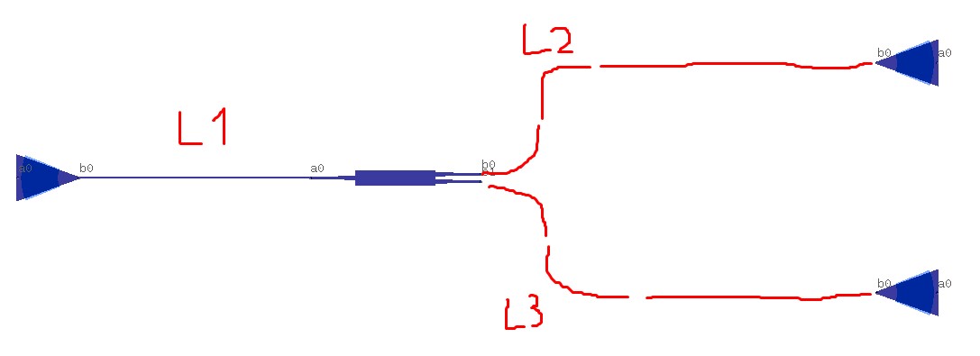 This is a fairly simple case, but in practice it is more difficult to create interconnects. As for example in this structure:
In red rectangles, elements that are created using cells and are added multiple times. These elements must be connected by waveguides, while adjusting the length of L1 with a certain step. It would be convenient to do as shown by the dotted line. If I add each section of the waveguide manually, then I encounter problems as the direction of bend:

What else can I try in such cases?22 May 2021 at 10:44 #6510Ronald
KeymasterDear Ruslan,
Good to hear Nazca works well for you.
Starting with your last image: Nazca uses outward pointing connections by definition. If you define your own block/cell, make sure you define pins pointing outwards from the circuit element. This would never lead to confusion of bend directions. Bend directions follow the standard mathematical convention of positive angles for counter clockwise rotation. Moreover, Nazca avoids quite nasty global layout states, e.g. no global cross section or global flip states, nor mixed in- and outward pin/port directions as mentioned above.
For the dotted L1 line case, you can just add an upward bend to the two blocks you connect this particular shape to. Connect the two bends with
ubend_p2p(length=L), where L is the length of the straight section, like in a sliding trumpet, used to extend the shape.For length extraction in two port elements/cells you can use the nd.trace module, for geometrical path lengths. To optimize the length of a section you can use a root or minimizer solver, as discussed in this trail_cellpost. The trial cell decorator shown there will be part of the nd.bb_util module in Nazca >0.5.13. (
@nd.bb_util.trial_cell).If you want to trace through interconnects and blocks/cells you can resort to the pathfinder module. That would need a dedicated tutorial to explain how to use it though. It can handle geometrical, optical and electrical path information.
Ronald
24 May 2021 at 12:07 #6515ParticipantDear Ronald,
Thank you for your answers! The recommendations are really useful and I can succeed.
-
AuthorPosts
- You must be logged in to reply to this topic.